Elegant diagrams (not haunted)
Haunted manuals, part 2, being a digression through circuit diagrams
by
Last week, I wrote about haunted manuals, and used the Operator's Instructions for Caterpillar Diesel D318 Engine and Electric Set (Serial numbers 5V5001 - Up, 3V5001 - Up) as a counterexample of a haunted manual. I had initially expected that it would be haunted, that is, that ghosts of previous versions and disagreements, and fears, and editorial battles, and lawyer's interventions, and perhaps workarounds would show themselves in hedges and lacunas and cautions. But no! The D318 manual is self-consistent, confident, and full of beautiful illustrations and diagrams. I particularly like the circuit diagram in the Electric Set section of the manual.
So, I scanned a bunch of them to share. The yellowing and stains lend them a certain charm, I think. I don't know how to interpret circuit diagrams. Nonetheless, I can appreciate the clear lettering that remains perfectly legible even though age and staining and the distinctive line drawings. Maybe someone who can read circuit diagrams can tell me what you think of them from a technical point of view.
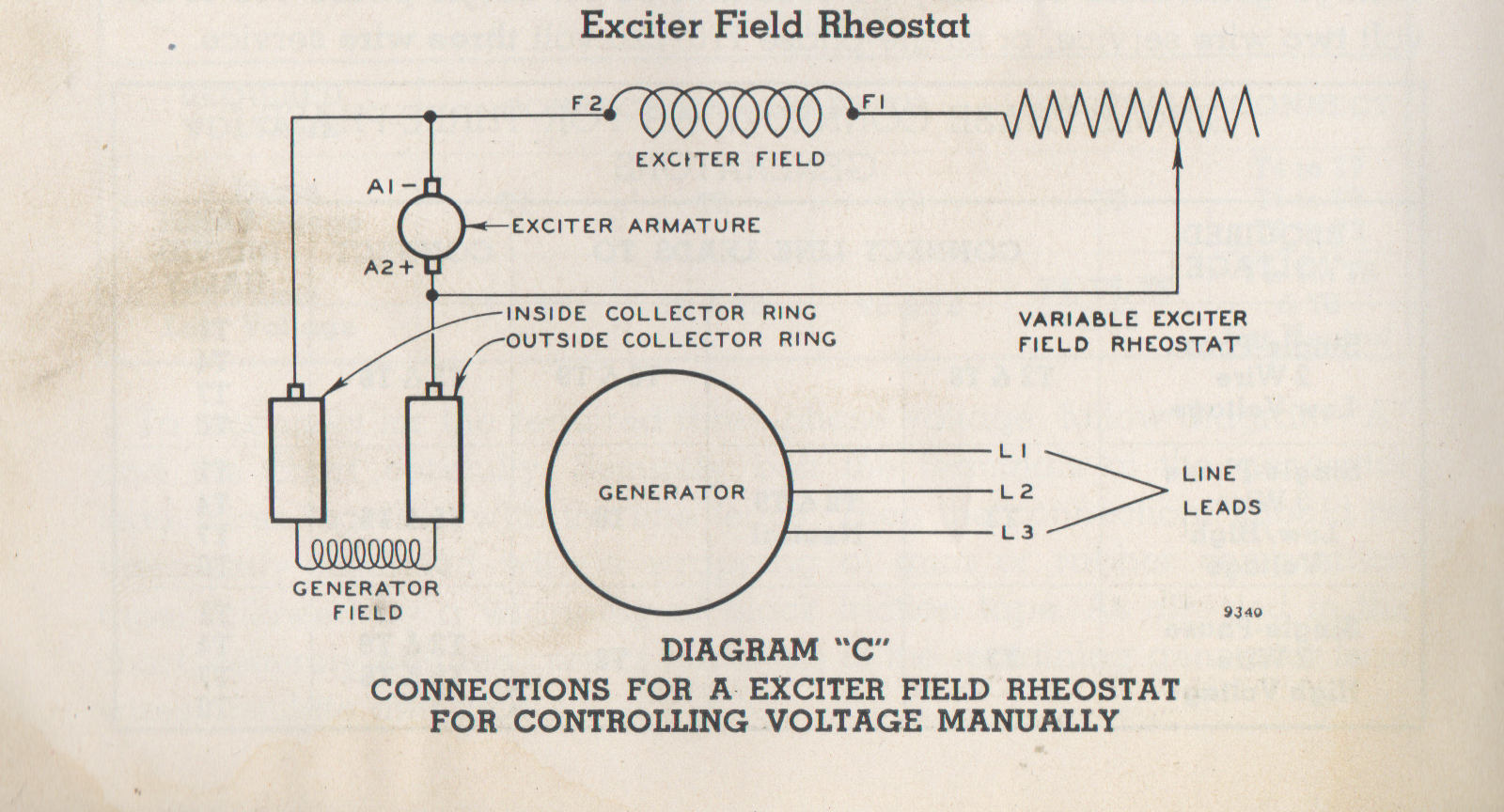
Exciter Field Rheostat. Diagram "C". Connections for a exciter field rheostat for controlling voltage manually. (Page 70)
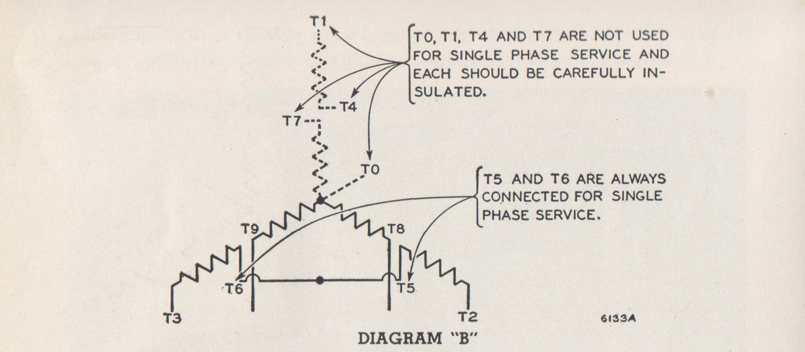
"Single-phase connections are given in Diagram 'B'" (Page 70)
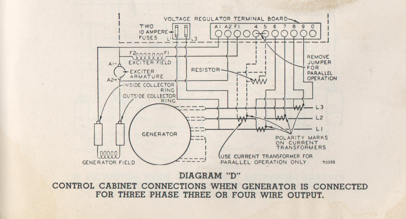
Diagram "D". Control cabinet connections when generator is connected for three phase or four phase wire output. (Page 71)
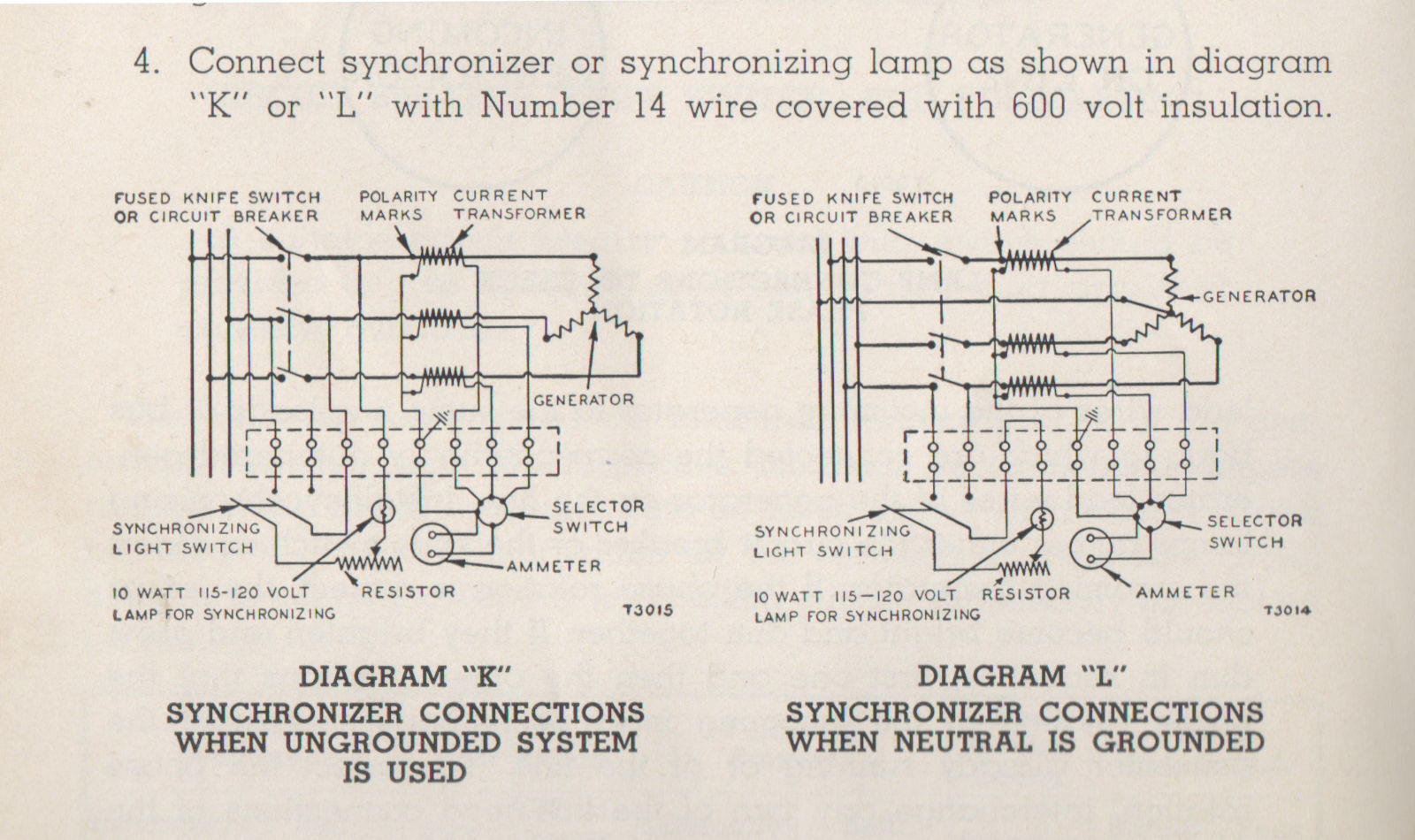
Connect synchronizer or synchronizing lamp as shown in diagram "K" or "L" with number 14 wire covered with 600 volt insulation.
Diagram "K". Synchronizing connections when ungrounded system is used.
Diagram "L". Synchronizing connections when neutral is grounded. (Page 76)
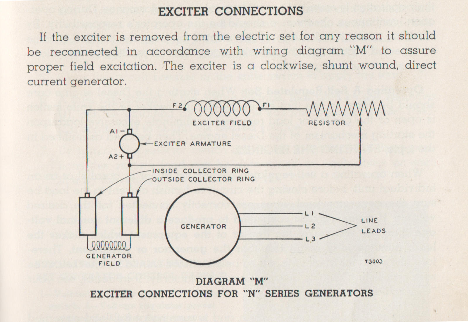
Exciter connections. Diagram "M". Exciter connection for "N" series generators. (Page 77)
"Proper field excitation" sounds like something you might hear about in the context of magical ritual or an obscure artistic process. Presumably, here it means something physical and measurable.
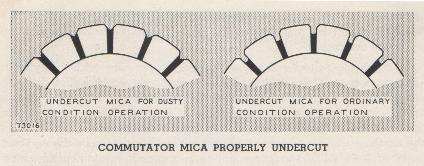
Undercut mica for dusty condition operation. Undercut mica for ordinary condition operation. Commutator mica properly undercut.(Page 86.)
This one isn't a circuit diagram but a schematic drawing. I don't know what a commutator is and I can't quite figure it out from context. I like how it looks like two stone arches or some kind of rainbow with teeth. The section directly preceding talks about the colors it might safely turn (copper, chocolate, black) and the colors you should worry about (green, blue, blotchy).
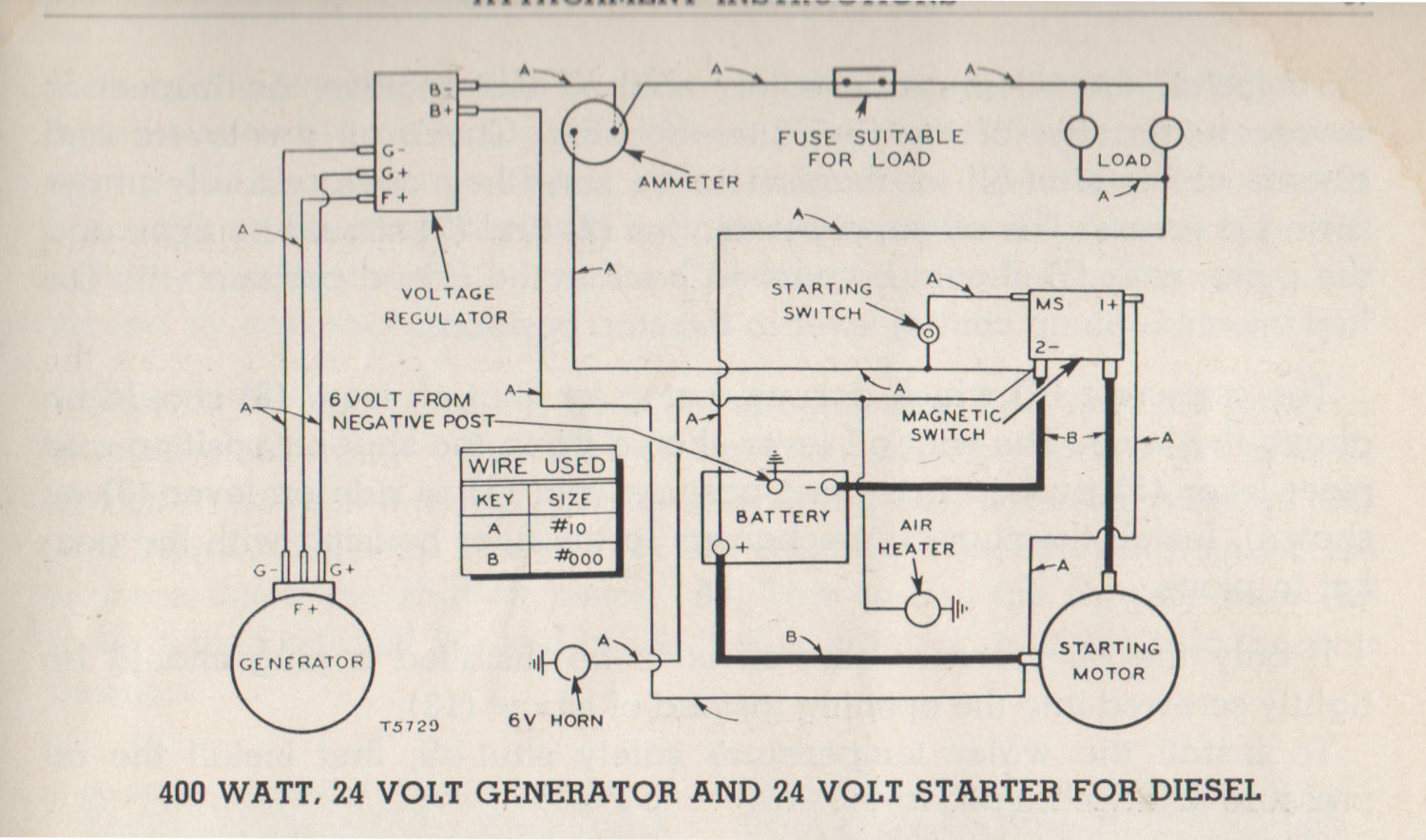
400 watt. 24 volt generator and 24 volt starter for diesel. (Page 97.)
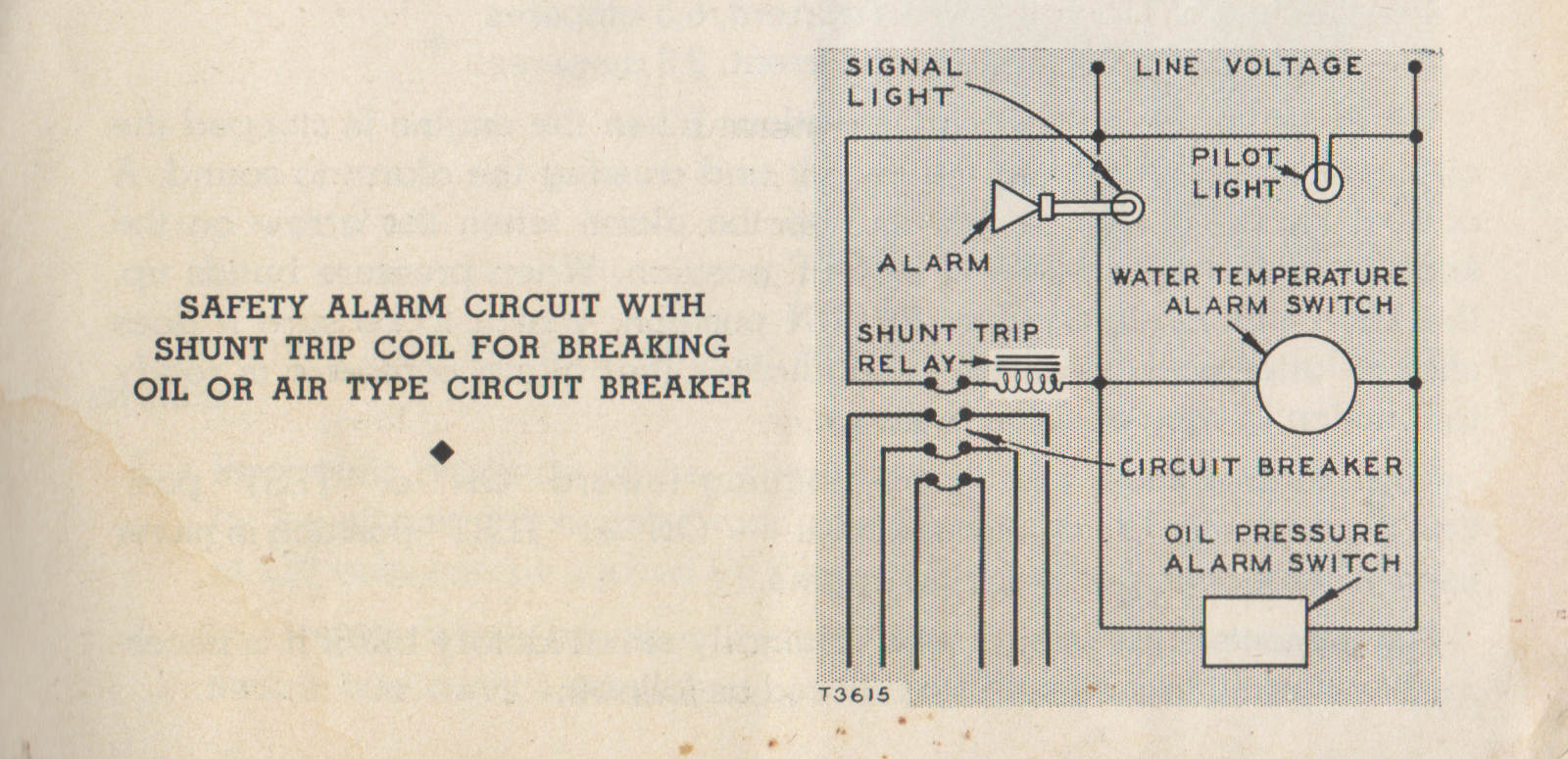
Label on the side: Safety alarm circuit with shunt trip coil for breaking oil or air type circuit breaker. (Page 101.)
The haunted manuals series #
- Haunted manuals: You've heard of the curse of knowledge, but could your manual be haunted as well?
- Elegant diagrams (not haunted): Haunted manuals, part 2, being a digression through circuit diagrams < You are here
- A taxonomy of old haunted manuals: Your manual is haunted. But how, exactly? (Haunted manuals part 3)
